Thursday, November 8, 2007 - 4:20 PM
612c
Ngnp Process Heat Utilization: Evaporative Spiral Heat Exchanger Design
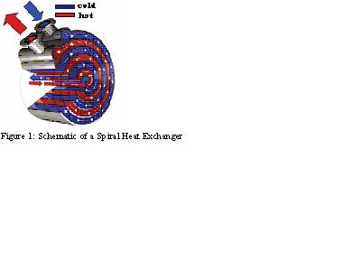
Spiral heat exchanger (SHE) designs as shown in figure 1, are less susceptible to fouling, and are more compact than conventional shell and tube designs resulting in reduced heat losses. Due to curvature of the tube, a centrifugal force is generated as the fluid flows through the curved tubes. The curved channels create a swirling or spiraling motion within the fluid. This spiraling motion helps keeps the solid present in fluid in suspension, and the heat transfer surfaces are kept clean through a scrubbing action. The flow is generally turbulent, even when flowing at velocities that would otherwise make the flow non-turbulent in straight tubes. Secondary flow induced by the centrifugal force has significant ability to enhance the heat transfer rate. SHE have been extensively used in a wide variety of applications for example, air conditioning and refrigeration systems. Heat transfer characteristics of SHE can be enhanced through manipulation of channel dimension (i.e. by varying the diameter of the pipe) and surface modifications by adding roughness to the pipe.
The SHE could be efficient phase change exchangers. The specific volume change from convective evaporation and condensation is well accommodated by the spiral design. Liquid flows into the eye of the spiral, gains heat, and vapor exits from the spiral ‘horn' for transport to the distant condenser at the industrial end user.
In this paper the case study is presented for the evaporative SHE design, where the transfer of thermal energy of the NGNP will be utilized for the boiling of sodium and further this heat will be used in the production of hydrogen. The approach to the development of the model involves writing energy balance equations for the two fluids over a differential element of the SHE. Figure 2 shows the flow paths of the two fluids and clarifies the basis for modeling of the SHE.
Figure 2: Flow Paths in the SHE
The energy balance equations for the hot and cold fluid are [2]:
(1) (2)
where CH and CC are the heat capacity rates (products of mass flow rates and heat capacities), q are the heat fluxes, t are the dimensionless temperatures, and φ the differential angle over which the energy balance is written. The subscripts i, j and r refer to the spiral positions.
Some of assumptions typically made for developing the mathematical models for the SHE are [6]: o The flow is fully developed for both the hot and cold streams, i.e. in the eye of the spiral or at center region we have gas (helium) and liquid (sodium), whereas at the periphery we have gas (helium) and vapor (sodium). o The fluid physical properties are uniform in each phase i.e. they are invariant for liquid sodium and also for sodium vapor, though the properties of liquid sodium are different than that of sodium vapor. o Radiative heat transfer is negligible o Heat losses from the outer surface to the surroundings are negligible o Thermal resistance of the channel wall is negligible
The energy balances shown above will be refined by removing restricting assumptions and developed further to model the performance of the SHEs. Variations and descriptions of SHE designs are also noted in the literature [1,4,5].
The study carried out in the paper provides valuable insight and options useful in the design and development of NGNP process heat utilization.
REFRENCES
1. Alfalaval, available on-line at www.alfalaval.com, January 2006
2. Bes, Th, and Roetzel, W., Thermal Theory of the Spiral Heat Exchanger, Int. J. Heat Mass Transfer, 36:765-773, 1993.
3. Davis C.B., Oh, C.H., Barner, R.B., Sherman, S.R., and Wilson, D.F. Thermal-Hydraulic Analyses of Heat Transfer Fluid Requirements and Characteristics for Coupling a Hydrogen Production Plant to a High-Temperature Nuclear Reactor, INL/EXT-05-00453, 2005.
4. Deshpande, S., Spiral Heat Exchangers, Chem. Eng. World, 28(2):81-83,m 1993
5. Dongwu, W., Geometric Calculations for the Spiral Heat Exchanger, Chem. Eng. Technol., 26:592-598, 2003.
6. Targett, M.J., Retallick, W.B. and Churchill, S.W., Solutions in Closed form for a Double-Spiral Heat Exchanger, Ind. Eng. Chem. Res., 31:658-669, 1992.