
 Google
 Yelp
 Facebook
 Twitter
 ChEnected
276566 Control of a Proton Exchange Membrane Fuel Cell, DC-DC Power Converter, an Ultracapacitor System Using Sliding Mode Controls
Control of a Proton Exchange Membrane Fuel Cell, DC-DC Power Converter, an Ultracapacitor System Using Sliding Mode Controls
|
Roshini.S. Ashok and Yuri B. Shtessel, Department of Electrical and Computer Engineering and James. E. Smith, Jr, Department of Chemical and Materials Engineering, The University of Alabama in Huntsville, Huntsville, AL 35899 |
In this paper we consider control of a power system that comprises three controlled components: Proton Exchange Membrane fuel cell (PEMFC), ultracapacitor, and a boost DC-DC power converter, using sliding mode control techniques. Control of fuel cells using sliding mode control (SMC) technique (Levant, A., (1993), Fridman, L. and Levant, A., (2002) and Shtessel, Y., et. al., (2011)) that is robust to the fuel cell model uncertainties and the external disturbances is studied in Sabanovic, A., et. al., (2004). Sliding mode control design for power systems, which consists of fuel cell and boosts DC-DC power converter, is presented in (Spurgeon S. and Davies, R., (1993), Shtessel, Y. and Ashok, R.S., (2011)). The use of ultracapacitor was addressed in the work (T. Azib, et. al., 2010). All three subsystems are controlled to provide a required power system's performance.
I. PHYSICAL DESCRIPTION OF PEMFC
The schematic of a Proton Exchange Membrane (PEM) fuel cell has two electrodes (anode and cathode) isolated by a membrane acting as an electrolyte as shown in Figure 1. (Matraji, I. 2010).
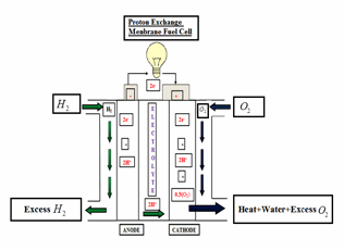
Figure 1. Schematic of a Fuel Cell Operation
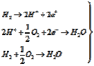
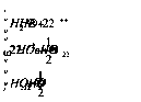
The performance of a PEM fuel cell increases, when its operating temperature is around 70-800C at a partial reactant pressure of 3-5atm. The chemical reactions in PEMFC can be described by the following equations (Larminie J. and Dicks, A. (2003), Kunusch, C. (2006)).
QUOTE
II. MATHEMATICAL MODELS
The mathematical model of the fuel cell electric power unit is derived dynamically, by combining the thermodynamic flow rate, boost DC-DC power converter and the ultra-capacitor. A typical PEMFC has the following V-I characteristic or polarization curve as shown in Figure 2.
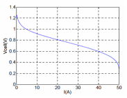
Figure 2. V-I Characteristics of the Fuel Cell
The voltage across the fuel cell (


where


A. Reversible Cell Voltage
The
open circuit voltage

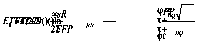
where




B. Activation Over Potential
Slow transfer of charge at the electrodes causes this loss. A part of the electrode potential is used for electron transfer to match the current demand. Hence the voltage at the fuel cell drops by;

where


The double layer of charge (dl) is needed to understand the dynamics
of the fuel cell. Whenever two materials of opposite charge come in contact,
there is an accumulation of the charge on the surface. The
charge layer that is deposited on the interface of the electrode or electrolyte
acts as storage of the electrical charges and acts as an electrical capacitor

C. Ohmic Over Potential
The ohmic over
potential


D. Concentration over potential
The electrical current and the physical characteristics of the system are directly proportional to the pressures of the oxygen and hydrogen. Maximum current density is used to determine the voltage drop, under which the fuel is being used at the same rate. Thus, the drop in voltage is caused due to the mass transport,

where coefficients vary with the temperature and are given to by;

A stack of 300 fuel cell units are used, along with an Ultracapacitor, are the primary source of electrical energy for the boost DC-DC power converter. The equivalent circuit (Larminie J. and Dicks, A. (2003), Kunusch, C. (2006)) is presented in Figure 3 below;


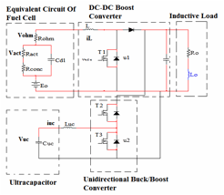
Figure 3. Circuit Diagram of Fuel Cell System


QUOTE


The system of electrical energy supply consists of the boost DC-DC power converter, which receives electrical energy from a stack of 300 fuel cell elements and is controlled by SMC and ASTW control is simulated. The parameters of the model are presented in Table 1.
Table 1. Model Parameters
Parameters | Values |
| |
| |
| 20 A |
| 10 V |
| |
| |
| 25 V |
| 125F |
| |
| 353 K |
| |


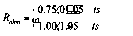
The load voltage command profiles were selected in accordance with (Sabanovic, A., et. al., (2004), Spurgeon S. and Davies, R., (1993) and Utkin, V., et. al., (1999)):
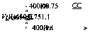
The
load resistor was changed at

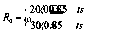
The
fuel cell varying resistor changed its value at

The simulation plots are presented in Figures
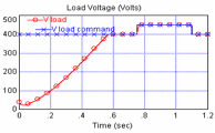
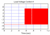
4-10. The plots on Figure 4
illustrate high accuracy direct tracking of the load voltage command profile
via classical sliding mode control (Figure 8) in the presence of unknown load
resistor while the voltage command profile is changing twice during simulation
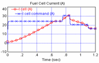
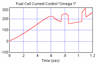
time. High accuracy tracking of the fuel cell current command profile that is
generated on line is confirmed via plots in Figure 5. The ultracapacitor current

Figure 4. Load Voltage | Figure 5. Fuel Cell Current |
Figure 8. Adaptive Control Gain | Figure 9. PEMFC Current Control |
Figure 10. DC-DC Boost Power Converter Control |
|
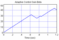



Two types of sliding mode control (traditional SMC and adaptive-gain 2-SMC, continuous super-twisting control) are used at the same time for controlling PEMFC power system. It is observed that a three-fold SMC feedback control structure (adaptive 2-SMC PEMFC current and traditional SMC voltage and ultracapacitor current controllers) avoids non-minimum phase property of boost DC-DC power converter, which output voltage is controlled directly and simplifies the controller design. The ultracapacitor not only acts as an auxiliary power source when there is an interruption in power supply but also responds rapidly to a fast load demands. The energy produced from a fuel cell is managed efficiently using appropriate Sliding mode control techniques. The efficacy and robustness of the SMC and 2-SMC controllers are confirmed via computer simulations.
V REFERENCES
Azib, T., Talj,, R Bethoux, O and Marchand, C. Member,IEEE.”Sliding Mode Control and Simulation of a Hybrid Fuel-Cell Ultracapacitor Power System”, 3425-3430, 2010.
Correa, J., Farret, F., Canha L., and Simoes, M., ”An Electrochemical-Based Fuel- Cell Model Suitable for Electrical Engineering Automation Approach”, Vol.51, NO.5, October 2004
Fridman, L. and Levant, A., “Higher Order Sliding Modes,” in Sliding Mode Control in Engineering. New York: Marcel Dekker, Inc., 2002, ch. 3, pp. 53–101.
Kunusch, C.,, “Second order sliding mode control of a fuel cell stack using a twisting algorithm,” M.S. thesis, Electr. Dept., Nat. Univ. La Plata, Argentina, Mar. 2006.
Larminie J. and Dicks A., Fuel Cell Systems Explained, 2nd ed. New York: Wiley, 2003.
Matraji, I., Laghrouche, S. and Wack, M., ”Second order Sliding Mode Control for PEM Fuel Cells”49th IEEE Conference on Decision and Controls, Atlanta, GA, USA, 2010.
Sabanovic, A., Fridman, L., and Spurgeon, S., Variable Structure Systems: From Principles to Implementation. London, U.K.: IEE, 2004.
Shtessel, Y and Ashok, R.S. “PEM Fuel Cell/ DC-DC Boost Power Converter System Control Via Traditional and Higher Order Sliding Modes,” Proceedings of the Conference on Decision and Control, 2011.
Shtessel, Y., Plestan, F. and Taleb, M., “Lyapunov design of adaptive super-twisting controller applied to a pneumatic actuator,” Proceedings of IFAC World Congress, Milan, Italy, August 2011.
Spurgeon S. and Davies, R., “A nonlinear control strategy for robust sliding mode performance in the presence of unmatched uncertainty,” Int. J. Control, vol. 57, no. 5, pp. 1107–1123, 1993.
Utkin, V., Gulder, J., and Shi, J., Sliding Mode Control in Electro-Mechanical Systems, London, U. K.: Taylor and Francis, 1999.
See more of this Group/Topical: Fuels and Petrochemicals Division