309065 Novel Fluid Grid and Voidage Calculation Techniques for a Discrete Element Model of a 3D Cylindrical Fluidized Bed

Monday, November 4, 2013: 3:33 PM
Golden Gate 6 (Hilton)
Christopher M. Boyce, Department of Chemical Engineering and Biotechnology, University of Cambridge, Cambridge, United Kingdom

Fluidized beds are used widely in industry, but despite this, the fundamental physics underlying fluidized beds is still not well understood. Computational modelling of fluidized beds has grown significantly recently, due in part to the drastic increase in computational power. An accurate model is advantageous because it can provide detailed time-averaged and instantaneous information on essentially all aspects of fluid and particle motion in fluidized beds. This paper describes the development and validation of a 3D cylindrical model incorporating novel fluid grid and voidage calculation methods to ensure accurate and stable simulations of fluidized beds.

Discrete element modelling (DEM) to simulate individual particle motion combined with computational fluid dynamics (CFD) to model fluid motion has proven an effective way to model laboratory size fluidized beds. Since it model particles individually, governed by contact and Newtonian mechanics, DEM-CFD provides a more accurate and insightful description of the particles in fluidized beds than do two-fluid models (TFMs) which treat the particles as a continuous phase. The main imperfection in DEM-CFD is that it requires a drag law to be used to describe the force of interaction between fluid and particles; however, more detailed models which do not require a drag law, such as direct numerical simulation (DNS), are too computationally expensive to model laboratory-scale fluidized beds.

Recently, researchers have been able to develop DEM-CFD models which go beyond simulating 2D rectangular beds and now model fully 3D cylindrical and more complex geometries. These models have generally used one of two techniques to simulate more complex geometries: (1) using a rectangular fluid grid with the immersed boundary method [1] or (2) using an unstructured fluid grid generated by a commercial CFD package, e.g. [2]. One difficulty associated with both methods is that it is very difficult to ensure that the fluid cells retain relatively equal volumes as well as reasonable shapes. In order to satisfy the assumptions made in deriving the volume-averaged fluid equations [3] used in DEM-CFD, it is necessary to ensure that the fluid cells are significantly larger in volume than the particles and do not have oblong shapes. If these criteria or not satisfied, the equations can break down, corrupting the solution.

An additional issue raised by using unstructured grids in DEM-CFD stems from trying to measure voidage in arbitrarily shaped CFD cells. Voidage is the volumetric fraction of a CFD cell free of particles, ideally defined as:

εcell = 1 – (ΣVparticles)/Vcell

 where εcell is the voidage of the cell, ΣVparticles is the total volume of all the particles in the cell and Vcell is the volume of the cell. This calculation needs to be accurate and stable in DEM-CFD because terms in the fluid equations and the drag law depend heavily on voidage. The main difficulty in calculating voidage stems from the fact that individual particles often lie in multiple fluid cells, and their volume must be divided between those cells. A crude approximation, here forward referred to as the direct method, would be to assume that the entire volume of a particle lies in a fluid cell if its centre lies in the cell. A method originally proposed for rectangular grids [4], here forward referred to as the grouping method, involves calculating voidage for each cell via the direct method and then reassessing the voidage for each cell by averaging its voidage with the voidage in all of its surrounding cells. This methodology was developed to add stability to the voidage calculation by spatially smearing the results and can be directly translated for use in arbitrarily shaped fluid cells. Another methodology for calculating voidage in rectangular grids [5], here forward known as the cuboid approximation, treats particles as being encapsulated by a cube, with the fraction of the volume of a particle divided into fluid cells being equal to the fraction of the volume of the cube located in the cells. This methodology provides stability and accuracy to voidage calculation in rectangular grids, yet it is not readily applicable to arbitrarily shaped fluid cells, since it is computationally expensive to divide the volume of a cube amongst arbitrarily shaped cells.

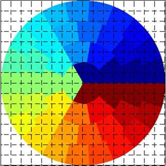
Thus a 3D cylindrical DEM-CFD model was developed here, using novel methods to address the issues of fluid cell volumes and voidage calculation associated with complex geometry models. A structured CFD grid in cylindrical coordinates was used, in which the length of cells in the radial direction remained constant, angle subtended by cells decreased with distance from the centre of the cylinder. This CFD grid conformation allowed the fluid cells to be kept with constant volume and reasonable shapes, to ensure the volume averaged fluid equations would be satisfied, while still fitting a 3D cylindrical geometry. Additionally, a novel voidage calculation technique, referred to as the “square grid” technique, was developed to stably and accurately calculate voidage in the cylindrical fluid cells. In this technique, voidage was first calculated on a square grid, using the cuboid approximation [5] to divide particle volume between square cells. Then, based on the fraction of each cylindrical fluid cell which lay in each square cell, calculated during initialisation, the voidage in each square cell was translated to calculate voidage in each cylindrical fluid cell. Figure 1 shows the cylindrical fluid grid setup with the square grid for calculating voidage overlaid.   

These novel techniques were built on top of the rectangular DEM-CFD code described in Müller et al.[6]. Particles were still modelled in rectangular coordinates, yet contained by cylindrical walls. Fluid particle interaction was modelled using the Beetstra et al. [7] drag law. Fluid velocities were converted into rectangular coordinates at the position of the particle of interest, in order to calculate the relative velocity between the fluid and the particle for calculating drag on the particles. The drag force was converted back into cylindrical coordinates to calculate the cumulative drag on the fluid.

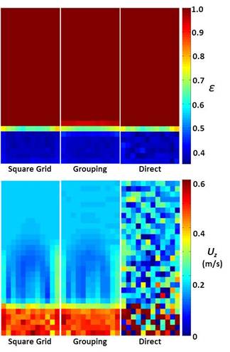
Figure 2 shows instantaneous voidage and vertical fluid velocity maps of steady state flow through a packed bed using the square grid, grouping and direct voidage calculation methods. While the voidage calculations are very similar, instabilities in the direct method caused even by minor movement in particles between cells in a packed bed, make its simulated fluid velocity unphysical.

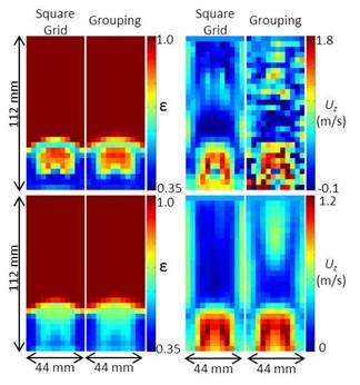
Figure 3 shows instantaneous and time-averaged voidage and vertical fluid velocity maps in a short bubbling fluidized bed using the square grid and grouping methods for calculating voidage. While both have similar voidage results and time-averaged fluid velocity results, only the square grid method shows the stability to physically simulate instantaneous fluid velocity.

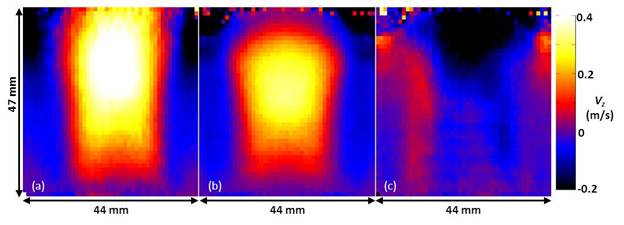
The 3D cylindrical DEM-CFD model was validated by comparison to MR experiments. Figure 4 shows a comparison of time-averaged particle velocity in a short bubbling bed; this comparison is discussed further elsewhere [8]. Additionally, DEM-CFD results for slug rise velocity in a tall slugging bed were compared to MR measurements [9] and theoretical values. Simulated slugs had rise velocities of 0.23 m/s and 0.25 m/s at locations 85 mm and 50 mm above the distributor in a 24 mm diameter bed with a settled height of 350 mm with an excess gas velocity U-Umf = 0.1 m/s. These results match those from MR experiments of the same bed [9], which determined that at these heights in this range of excess gas velocity, slug rise velocities should lie in between the theoretical values for wall and axisymmetric slugs of 0.19 m/s and 0.30 m/s respectively.

The validation of the 3D cylindrical DEM-CFD model by experimental results in vastly different fluidized bed systems lends confidence to its use in predicting behaviour in a wide variety of fluidized bed systems.

References:

[1] Guo, Y., Wu, C.Y., Thornton, C. (2012). A.I.Ch.E. J., 59, 1075-1087.

[2] Chu, K.W., Yu, A.B. (2008a). Powder Technology, 179, 104-114.

[3] Anderson, T. B., & Jackson, R. (1967). Industrial & Engineering Chemistry Fundamentals, 6, 527–539.

[4] Yu, A.B. (2006), A.I.Ch.E. J., 52, 496-509.

[5] Khawaja, H.A., Scott, S.A., Virk, M.S., & Moatamedi, M. (2012). The Journal of Computational Multiphase Flows, 4, 183-192.

[6] Müller, C.R., Scott, S.A., Holland, D.J., Clarke, B.C., Sederman, A.J., Dennis, J.S., Gladden, L.F. (2009). Particuology, 7, 297-306.

[7] Beetstra, R., van der Hoef, M. A., & Kuipers, J. A. M. (2007). AIChE J., 53, 489–501.

[8] Boyce, C.M., Holland, D.J., Scott, S.A., Dennis, J.S. (submitted 2013). Phys Rev E.

[9] Müller, C.R., Davidson, J.F., Dennis, J.S., Fennell, P.S., Gladden, L.F, Hayhurst, A.N., Mantle, M.D., Rees, A.C., Sederman, A.J. (2007). Chemical Engineering Science, 62, 82-93.
Figures:

Figure 1 Novel cylindrical CFD grid, each colour representing a different fluid cell, with square grid for voidage calculation overlaid.

Figure 2. Comparison of voidage calculation methods for packed bed flow.

Figure 3. Comparison of voidage calculation methods for instantaneous (left) and time-averaged (right) fluidized bed flow.

Figure 4 Comparison of time-average axial particle velocity images from: (a) experimental MR imaging and (b) DEM-CFD simulation of a bubbling fluidized bed. A difference map is shown in (c) (Reproduced from Boyce et al. [8])


Extended Abstract: File Not Uploaded
See more of this Session: Dynamics and Modeling of Particulate Systems III
See more of this Group/Topical: Particle Technology Forum