
 Google
 Yelp
 Facebook
 Twitter
 ChEnected
324193 Computational Fluid Dynamics Modelling of Single and Two-Phase Heat and Mass Transfer in Micro- and Milli-Scale Flows
Computational Fluid Dynamics modelling of single and two-phase heat and mass transfer in micro- and milli-scale flows
Simon Kuhn
Department of Chemical Engineering, University College London, UK
The investigation and characterization of heat and mass transfer phenomena in single and two-phase flow is important in understanding transport mechanisms influencing chemical reactions in micro- and milli-scale devices, where no (or only little) turbulent actions promote mixing and interfacial transport processes. This detailed analysis is accomplished by a rational approach, identifying the physical mechanisms of heat and interfacial mass transfer on various length-scales using non-invasive, laser-optical measurement techniques1-3, and to use these experimental results to validate and develop predictive multiphase flow models for computational fluid dynamics (CFD).
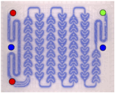
For this presentation we will focus on the CFD modelling aspect of the work, where we use the open-source software OpenFOAM¨ to predict single and two-phase flow heat and interfacial mass transfer on the micro-scale (i.e. 400 μm microchannels) and on the milli-scale. Our model geometry for the milli-scale is the Corning Advanced Flow Reactor (AFR) depicted in Fig. 1, which consists of several rows of heart-shaped cells in series.
|
Fig. 1 Representation of the Corning Advanced Flow Reactor geometry. The red dots represent the two inlets for the continuous and dispersed phase, the green dot the outlet. The plate volume is 8.7mL. |
The aim of these simulations is to understand interfacial transport processes in more detail, and to use this knowledge to design optimized milli-scale multiphase flow reactors. The developed models and obtained results will therefore directly impact the efforts in process intensification and sustainable advanced manufacturing.
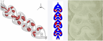
The numerical work is conducted using the volume-of-fluid (VOF) approach to simulate two-phase flows, which uses an indicator function α to describe the volumetric phase fraction in each computational cell. Since the phase interface definition is highly coupled to the mesh resolution extra terms are needed to account for numerical diffusion, and to provide a sharp interface definition. In the current version of the standard OpenFOAM¨ solver interFoam an interface compression approach is used, and in initial simulations we validated this implementation for the test case of bubble generation in a microfluidic T-junction against experimental results. It was found that the standard implementation is too diffusive, thus we introduced changes in the interface compression scheme to increase the interface sharpness, which then matched the experimental results and proved also successful on the milli-scale (see Fig. 2).
|
Fig. 2: Comparison of the gas-liquid flow distribution predicted by the modified VOF solver with experimental results from a high-speed camera. |
The standard interFoam solver does not include scalar transport processes, thus we implemented the energy equation in the VOF solver (the indices denote the gas (G) and liquid (L) phase respectively, and can be transformed to liquid-liquid systems as well):
 (1)
where μ denotes the dynamic viscosity of the fluid, and Pr is the Prandtl number defined as Pr= μcP/λ , with the thermal conductivity λ, and the heat capacity cp. This equation can be readily adapted for the VOF approach by calculating the fluid properties (ρ, μ, cp, and λ) using the phase fraction α.
The implementation of species concentration in the VOF framework uses the same approach, i.e. we define the concentration c and the diffusion coefficient D as
c= αcG+(1- α)cL; and D= αDG+(1- α)DL . (2)
The boundary condition at the interface between the gas and liquid phase is satisfied by Henry's law
cG=HcL (3)
with the Henry coefficient H describing the equilibrium solubility of the species in the liquid phase. However, as the VOF approach only solves a single species equation this needs to be taken into account as an explicit source term in the scalar transport equation, which then reads in the VOF framework
 . (4)
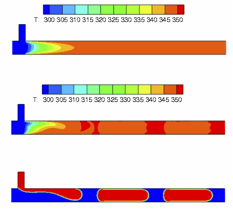
Figure 3 depicts the predicted temperature field in single and two-phase flow in a microfluidic T-junction. The fluids are brought in contact at even temperature and then heat up as they flow downstream in the microchannel. For the single phase case a parabolic temperature field is observed, which is expected for laminar convective heat transfer. The temperature field of the gas-liquid flow case reveals the influence of the bubble generation process in the entrance region of the microchannel on heat transfer. Initially the gas phase is still in contact with the wall and heats up faster than the liquid phase. After detachment of the gas bubble it is isolated from the wall by the thin liquid film surrounding it, which is expressed in the slight temperature difference between the gas and liquid phases further downstream.
|
Fig. 3: Comparison of single (top) and two-phase flow (middle) temperature fields in a microchannel. The bottom representation shows the distribution of the gas bubbles. |
|
Fig. 4: Comparison of single (left) and two-phase flow (middle) temperature fields in 4 hearts of the Corning AFR. The right representation shows the distribution of the gas bubbles. |
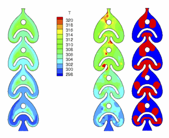
Figure 4 depicts the comparison of temperature fields for the Corning AFR. In single phase flow the individual heart design leads to considerable temperature gradients within a single cell. Elevated temperatures are observed in regions of low fluid velocity, these zones are characterized by a recirculating fluid motion, which develops between the U-shaped structure and the downstream post. These regions of warmer fluid are bypassed by fluid of lower temperature, thus this particular design leads to limited cross-mixing in single phase flow. These recirculation zones are not able to establish in two-phase flow due to the bubble dynamics (constant break-up and merging), and as a consequence the developing temperature field is much smoother and the heat transfer performance is increased, as seen by the higher average temperature in the final heart compared to single phase flow.
We will report in detail on the implemented VOF method, and the obtained heat and mass transfer data are validated against available experimental results and are further interpreted to characterize the transport processes on the micro- and milli-scale.
References:
[1] Kuhn, S.; Jensen, K.F. (2012) A pH sensitive Laser-Induced Fluorescence technique to monitor mass transfer in multiphase flows in microfluidic devices. Ind. Eng. Chem. Res. 51:8999-9006.
[2] Kuhn, S.; Woitalka, A.; Jensen, K.F. (2012) Mass Transfer in gas-liquid and liquid-liquid multiphase flows. Proceedings of the 3rd European Conference on Microfluidics.
[3] Nieves-Remacha, M.J.; Kulkarni, A.A.; Jensen, K.F. (2012) Hydrodynamics of Liquid-Liquid Dispersion in an Advanced-Flow Reactor. Ind. Eng. Chem. Res. 51:16251–16262.
See more of this Group/Topical: Engineering Sciences and Fundamentals