
 Google
 Yelp
 Facebook
 Twitter
 ChEnected
329724 The Effect of Pressure On Bubble Parameters in Jetting Fluidized Bed At High Fluidizing Gas Velocity
The effect of pressure on bubble parameters in jetting fluidized bed at high fluidizing gas velocity
Junguo Li, Zhonghu Cheng, Yitian Fang
State Key Laboratory of Coal Conversion, Institute of Coal Chemistry, Chinese Academy of Sciences, Taiyuan, 030001, P. R. China
Introduction
Lignite is abundant and makes up approximately 40% of coal reserves in the world. Commercial use of lignite is forecast to grow substantially owing to the occurrence of deposits in such countries as India, China, and Southeast Asia, which are experiencing the strongest growth in electricity demand.1 Also inferior anthracite and non-coking bituminous coal is abundant in China. What is worse, more than 50 percent of coal has a high ash melting point. Commercial use of the above mentioned coal is forecast to grow substantially owing to the lack of oil in China, which is experiencing the strongest growth in the development of coal chemical industry.2 However, inferior anthracite usually has high ash and sulfur content and high ash fusion temperature. In addition, lignite has high water and oxygen content, low energy density, being prone to weathering and spontaneous combustion. All these characteristics limit their high efficient utilization. Fortunately, fluidized bed is considered as a promising gas producing technology due to its better adaptability to the poor coal and effectiveness in the control of pollutant emissions. However, it has the disadvantages of difficult scale-up, and relative lower capacity. Considering the developed large-scale gasification technology is all on the base of increasing of pressure, the behaviour of gas-fluidized beds at high pressures is of interest from theoretical and practical points of view.
Jetting fluidized bed (JFB), another type of spouted bed, where the jetting phenomena is an important considerations, is the spouted fluid bed, especially when the jet does not penetrate through the bed like that in a spouted bed.3 One of the important applications of the JFB is the ash-agglomerating fluidized-bed coal gasifier (U-gas, KRW, and ICC). Several demonstration projects of this coal gasification process have been established in China and USA.4 Many researchers pay attention to the jet penetration depth; however, too few papers report on the bubble dynamic of the JFB. After all, bubble characteristics have been well recognized as one of the most important parameters of conventional gas-solid fluidized bed.
The present work aimed to perform experimental investigations on the bubble dynamic in a two dimensional JFB. It focused on systematically examining the effects of pressure, fluidizing gas velocity, jetting gas velocity and static bed height on the bubble parameters and its new correlation.
Experimental Setup
Apparatus and materials
Experiments were conducted utilizing a high-pressure fluidization cold model facility. Briefly the facility comprises a pressure vessel, a nitrogen supply system, CCD video cameras, a video imaging system, an optic fiber system and peripheral equipment. The pressure vessel, capable of operating at pressures up to 3.3MPa, is 1.6 m high with an inside diameter of 1.2 m. The interior of the vessel is lighted by internal LED lamps. The nitrogen supply system uses a high-pressure reciprocating pump. No nitrogen recirculation system is used. Supply pressure in the reciprocating pump is maintained by a central liquid nitrogen system. Flow control is accomplished by use of a parallel mass flow meter setup. The control valve is used for fluidized bed distributor as the fluidized gas, and the control valve is used for jetting tube as the jetting gas. An upstream pressure control valve and a back pressure control valve are used to maintain the system pressure. Experiments were carried out in a 2D Plexiglas jetting fluidized bed which has a cross section of a = 300 mm, b = 30 mm and total height of 1450 mm (see Fig. 1). The area of jetting nozzle is c = 50 mm, b = 30 mm and height l3 = 400 mm. A V type gas distributor which has a b = 90 ° conical angle and height l2 = 100 mm was located at the bottom of the bed and the total area of all orifices is 1.2%.
The bed material was polystyrene with the sphericity close to 1. The mean particle diameter was 1.32 mm and the particle density was 1020 Kg/m3, which is close to the group B/group D boundary using Geldart's definition. The minimum fluidization velocity, umf, was then determined from the plot of pressure drop vs. velocity of nitrogen in the traditional way at 0.7, 1.1, 1.6 and 2.1 MPa. The terminal velocity, ut, was then determined from the terminal velocity of a falling particle under different pressure. A summary of experimental conditions and the particles fluidization properties studied in this work were listed in Tables 1 and 2, respectively.
Video imaging system and image processing
The low-cost CCD cameras which are able to work under pressure are customized and the image is clear under lower pressure. However, as the pressure increases, the density and refractive index of the gas are constantly larger and camera image becomes increasingly blurred. Fortunately, changing the focal length appropriately, the image becomes clear again under higher pressure. In the experiment three groups of CCD cameras which have different focal length are installed to observe bubbles and solids motion form in the high-pressure fluidization cold model facility. The image of the first group cameras is clear only under lower pressure (0.1 - 0.7 MPa), the second is clear under middle pressure (0.8 - 1.4 MPa), and the last is clear only under higher pressure (1.5 - 2.1 MPa). The cable, sealed in the flange, is capable of transmitting imaging signal to an external video imaging system. And then the films of digital video image from the video camera are transferred to PC computer. With the image processing toolbox of Matlab, the software is developed to automate the procedures for picture acquisition, data processing and analysis for frame by frame. Then the data about bubble diameter in the bed is acquired.
Table 1 Experimental conditions
P (MPa)
| H0 (mm)
| uf -umf (m/s) | uj / ut |
0-2.1
| 240-300
| 0.2-04
| 0.8-1.5
|
Table 2 Minimum and terminal velocities in fluidization of polystyrene under pressure
P (MPa)
| umf (m/s)
| ut (m/s) |
0.7
| 0.19
| 2.10
|
1.1
| 0.16
| 1.68
|
1.6
| 0.13
| 1.39
|
2.1
| 0.11
| 1.21
|
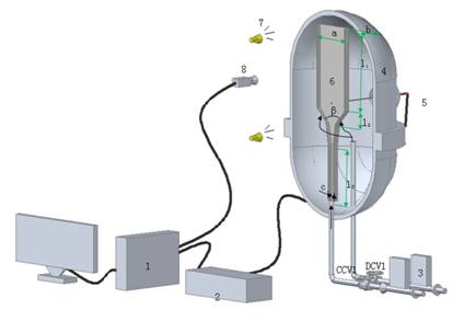
Fig. 1. Scheme of the experimental set-up. 1-computer; 2-data processing system; 3-mass flow meter/controller; 4-pressure vessel; 5-optical fiber probe; 6-two dimensional jetting fluidized bed; 7- LED lamps; 8-CCD camera.
Results and Discussions
Experimental data about bubble equivalent diameter distribution versus height above the top of air distributor at 2.1 MPa are presented in Fig. 2 for an identical static height of H0/D = 0.87, jetting gas velocity uj = 1.25 ut and fluidizing gas velocity uf - umf = 0.20 and 0.3m/s. It is shown that with the increase of bubble height or fluidizing gas velocity, bubble diameters almost keep constant. It may be due to the effect of jetting gas velocity. In the jetting fluidized bed, the jetting gas is very high and almost occupies half of the total gas.
To highlight the trend of bubble growth along bed height, the arithmetic average bubble diameters are also plotted in Fig. 2. It is reflected that the average diameters remain stable and then decrease at the top of jetting fluidized bed. The reason may that the equilibrium between the coalescence and splitting of bubbles is broken up. The bed is in the turbulent regime.
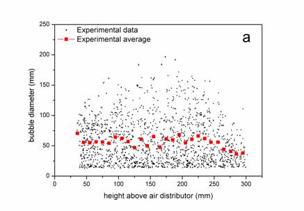
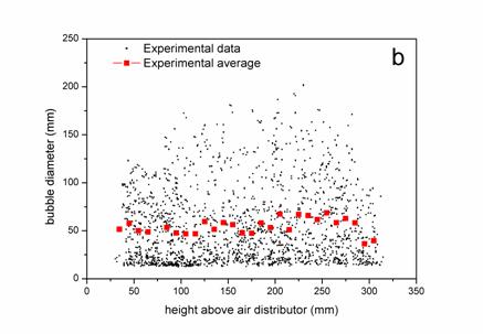
Fig .2. Bubble diameter distributions as a function of height above the distributer at 2.1 MPa: (a) uf - umf = 0.20 m/s, (b) uf - umf = 0.30 m/s.
The systematically effects of pressure, fluidizing gas velocity, jetting gas velocity and static bed height on the bubble parameters and its new correlation will be presented in the congress.
Notation
D Width of 2-dimensional jetting fluidized bed, mm
H0 Static bed height, mm
uf Fluidizing gas velocity, m/s
uj Jetting gas velocity, m/s
umf Minimum fluidization velocity, m/s
ut Terminal velocity of a free-fall particle, m/s
Literature Cited
1. Chadwick BL. Development and application of an on-line fouling gauge for brown coal power stations. Industrial & Engineering Chemistry Research. Mar 1999;38(3):1159-1162.
2. Li FH, Huang JJ, Fang YT, Wang Y. Formation Mechanism of Slag during Fluid-bed Gasification of Lignite. Energ Fuel. Jan 2011;25:273-280.
3. WC Y. Fluidization, Solids Handling, and Processing: Industrial Application. Noyes Publication. 1998.
4. Zhang K, Zhang J, Zhang B. Experimental and numerical study of fluid dynamic parameters in a jetting fluidized bed of a binary mixture. Powder Technology. 2003;132(1):30-38.
See more of this Group/Topical: Particle Technology Forum