
 Google
 Yelp
 Facebook
 Twitter
 ChEnected
333203 Numerical Simulation and Experimental Study On Fouling in the FCC Flue Gas Turbine
Numerical Simulation and Experimental Study on Fouling in the FCC flue gas turbine
Yupeng Du, Hui Zhao, Chaohe Yang, Renbo Hu
State key laboratory of heavy oil processing, China University of Petroleum, Qingdao, China
Introduction
The fluid catalytic cracking (FCC) flue gas turbine is a typical turbo-machinery and an essential device of the power recovery unit in FCC processing. It functions as converting the high-temperature heat energy and high pressure energy of exhaust gases generating from carbon burning on catalysts in FCC regenerators to mechanical energy, to drive the main air blower or the generator to recover energy contained in flue gas. Nevertheless, over recent years an urgent issue has been put on the agenda: catalyst scaling on the inner parts of the flue gas turbine, which has a considerable influence on the long-run of FCCU. We have surveyed 87 refineries in China, out of which 59 refineries confronted with this trouble 1. Although some researches on this issue have been published 2-4, the fundamental mechanism and solution to this problem are still remained as a problem.
Numerical Methodology and Experimental analysis
The Euler-Lagrange multiphase approach was adopted for this investigation. The conservation equations of mass, momentum, and energy are solved for gaseous phase by using Euler's model, while particle trajectory equations of solid phase are solved by employing Discrete Phase Model (DPM) with Discrete Random Walk model (DRW). Besides, SST k-ω model was used as the turbulence model for gaseous phase because of the SST k-ω model is more accurate and reliable for a wider class of flows (e.g., adverse pressure gradient flows, airfoils, transonic shock waves) 5. The simulation cases were carried out on an equal-radius quasi-three-dimensional plane of blading cut from a single-stage axial flow turbine (Figure 1). Typical dimensions for main structure could be described as: Blade pitch was 0.05m, Chord length was 0.05m, and Gap distance is 0.02m Four gaseous species (O2, H2O(g), CO2, and N2) and one solid specie (catalyst fines) had been defined as the model. Based on this model, gaseous phase fluid fields were numerically studied and the trajectories of entrained particles with various diameters were calculated; particle depositions on the rotor blades were investigated and analyzed numerically as well.
With the simulation results to be validated, the physical and chemical characteristics of catalysts and fouling samples were analysed by means of analytical instruments, including X-ray diffraction (XRD) for analyzing mineral compositions and scanning electron microscope (SEM) for analyzing the micro-morphology of samples.
Results and Discussion
Typical flow field between stator and rotor was shown as Figure 2. It could be found that the velocity on the pressure side of both stator and rotor was lower than that on other places. While, there were higher moisture content and temperature field on the pressure-side of the rotor than other places. Much longer particle-wall interaction time (e.g. Van der Waals' force and electrostatic force) could be expected from lower flow velocity, and so more readily particles migrate towards the wall as well. Under a circumstance of high moisture content and temperature, certain substrates, such as Ca, K, Ni, V and CaCl2, on the surface of catalyst are apt to form eutectic mixture, resulting in the catalyst particles become stickier 6. The formed eutectic mixtures could also function as one kind of binders, which enhance particles adhering junction and meantime absorb follow-up catalyst agents flowing nearby, leading to more particles conglutination and melting there.
The predicted fouling positions induced by particles with two different diameters (1µm, 3µm) were shown in Figure 3. In fact, the particle concentration in flow passage of flue gas turbine was extremely low. However, in the current study, the stack concentration of catalyst particles has been increased multifold for clarifying the different behaviors of different particles. Obviously, particles with 3µm form a particle concentrated area on the pressure-side of rotors, while particles with 1µm are well-distributed. However, 1µm particles closed to the rotor surface also readily accumulated there. The predicted particle deposition locations induced by catalyst particles were shown in Figure 4(B) and 4(C), while Figure 4(A) showed practical fouling locations on rotors in a practical flue gas turbine. Basically good agreement could be found from comparison between each other.
Comparisons between two XRD result were shown in Figure 5, remarkable difference could be observed: the peak that indicated the of crystalline for equilibrant catalyst in Figure 5(A) disappeared, instead of which an amorphous peak of fouling sample occurred in Figure 5(B). The main reason for this transition could be concluded as the deposited particles on the walls melt or sinter at the high-temperature circumstances, the same conclusion can be inferred as shown in Figure 6. From SEM spectrograms of fouling samples in figure 5, catalyst accumulation zones and compact melting zones with a large scale can be observed. We also found the melting zones on the flow-side of fouling were much larger than that on the other side due to the influence of much higher temperature on the flow-side of fouling.
Conclusions
According to the simulation results and instrumental analyses mentioned above, detailed fouling procedure inside the FCC flue gas turbine could be proposed: Firstly, some gaseous melted components condensed when they collide with walls (such as gaseous vanadic fusant), and wetting the vicinity, so the original layer comes into being; Secondly, small particles (3µm or even smaller) concentrate on the pressure-side of rotors, and thicken the deposition layer. Meanwhile, heat resistance increases, which may lead to the temperature of fouling more approximated to that of the gaseous phase. Finally, under a high temperature, more melted matters strengthen their stickiness. Besides, with the help of the condensation of cooling steam from the turbine bearing block, more catalyst fragments could be captured. Likewise, these three steps take place sequent. As a consequence, catalyst fouling in turbine.
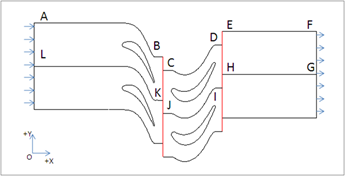
Fig.1 Geometric model and simulation domain
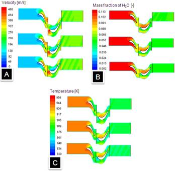
Fig.2 Flow field and profile of (A) Velocity, (B) Molar concentration of H2O, and (C) Temperature btween stator and rotor
SHAPE \* MERGEFORMAT
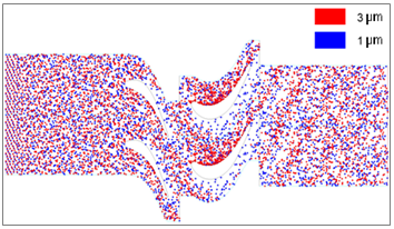
Fig.3 Distribution of particles with different diameters among blade rows
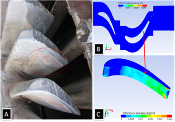
Fig.4 (A) Practical fouling locations, and (B),(C) predicted deposition locations on rotors.
SHAPE \* MERGEFORMAT A B
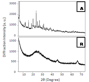
Fig.5 XRD Patterns of (A) Equilibrium catalyst and (C) Fouling sample
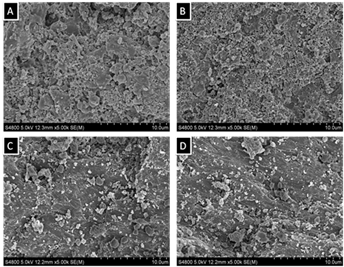
Fig.6 SEM spectrograms of (A and B) Underside of fouling and (C and D) Upside of fouling
References
1. Renbo Hu, Rui Bai, and Ming GAO (2012), "Fouling Status and Reason Analysis of FCC Expander," 40th annual conference of National Technology Center of Chemical Engineering Design, pp. 282-287.
2. Dianguo Hou (2011), "Analysis on Causes of Scaling in Flue Gas Turbine of FCC and Countermeasures," China Petroleum Processing and Petrochemical Technology, 13(1), pp. 66-74.
3. Pengfei Lu, J. Ji, and L.W. Yang (2008), "A study into deposition, erosion and corrosion properties of flue gas turbines," Sino-Global Energy. (s1).
4. Yun Xu, Yuxia Zhu, and Huiping Tian (2010). "A Probe into Causes and Remedies for Flue Gas Turbine Fouling in FCCU," Industrial Catalysis,18(3), pp.56-60.
5. Menter Florian R. (1994), "Two-equation Eddy-viscosity Turbulence Models for Engineering Applications," AIAA Journal, 32(8), pp.1598-1605.
6. Atul Sharma, V.V. Tyagi, C.R. Chen (2009). "Review on Thermal Energy Storage with Phase Change Materials and Applications," Renewable and Sustainable Energy Reviews. 13(2), pp.318–345.
See more of this Group/Topical: Particle Technology Forum