
 Google
 Yelp
 Facebook
 Twitter
 ChEnected
467208 Furfural Production By Continuous Reactive Extraction
1. Introduction
The bio-based economy grows rapidly during the 21st century. So far, oil and natural gas dominate the industrial world and are widely considered as raw materials. During the last few years, the use of biomass as raw material has increased significantly (1).
One important renewable bio-based chemical is furfural. It is widely used as solvent for saturated hydrocarbons because of its chemical structure. Moreover, it has the ability to dissolve aromatics and other unsaturated olefins (2) and is extensively used in oil and gas industry. Finally, furfural has a high potential as a platform chemical.
The objective of this study is to investigate the reaction mechanism and kinetics of xylose conversion towards furfural production by a continuous reactive extraction process. Moreover, the reaction pathway will be further elucidated and the kinetic rates of the intermediate steps are determined. Finally, the kinetic model for xylose dehydration to furfural is used to maximize furfural yield.
2. Experimental section
2.1.Reaction mechanism
The conversion of xylose to furfural is quite complex. Several studies (2), (3) have been performed in order to analyze and interpret the mechanism of the xylose dehydration. The scheme below shows the suggested mechanisms.
|
|
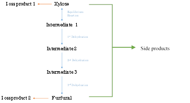
Scheme 1 Reaction mechanisms of xylose dehydration (2), (3)
According to Scheme 2 (blue), xylose is in equilibrium with intermediate I1. I1 undergoes three dehydration reactions to furfural. Byproducts are formed directly from either xylose or furfural (orange). The furfural degradation to byproduct 2 is significant and influences the selectivity. Increasing the temperature and acidity will further catalyze the degradation. An additional reaction is mentioned in (3), where xylose and furfural react and form side products (green).
The formation of byproducts from furfural can be reduced by in situ removal of furfural from the aqueous solution, by evaporation (4) or by extraction. Various studies (3), (4) have been performed to investigate which solvent performs best. Toluene and MIBK seem the most promising candidates with high affinity to furfural. Therefore, in this study, toluene is selected.
2.2.Experimental Setup
The experiments are performed in a biphasic continuous reactor as shown in Scheme 2. The configuration includes 3 pumps for sulfuric acid, xylose solution, and toluene. The maximum total flow is 15 mL/min and the minimum flow is 4 mL/min, with the flow ratio organic/aqueous of 2:1.
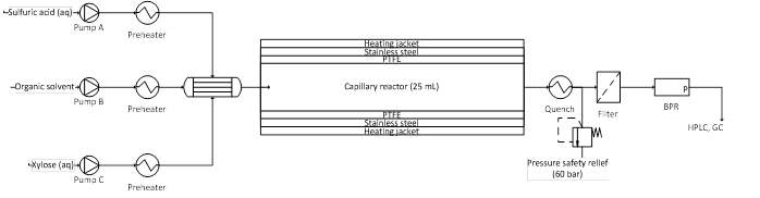
Scheme 2 Experiment lay out
The three streams flow separately in stainless steel tubes of 1.5 m length and 0.5 mm inner diameter through a heat exchanger to acquire the desired temperature. The preheat system is followed by two consecutive T-joints that allow the capillaries to be inserted in each other. Therefore the three streams are injected and mixed at the reactor’s entrance (Scheme 3).

Scheme 3 Reactor inlet flow development
The reactor of 1.5 m in length and an inner diameter of 3.1 mm consists of a PTFE wall and a stainless steel mesh jacket to provide structural integrity. The PTFE wall is hydrophobic and wetted by toluene only, which prevents solid deposition at the reactor wall. The mixture is then quenched followed by a pressure safety relief and a filter with 2 μm pores that protects the back-pressure regulator (BPR) from blocking by solids formed during the reaction. Samples are taken after the BPR at atmospheric pressure and ambient temperature and analyzed with HPLC (aqueous phase) and GC (toluene phase).
The temperature range of the experiment is 100-170oC and the pressure is 30 bar so the presence of any vapor or gas at the working temperature is avoided. The selected catalyst is sulfuric acid (98%, Emsure) at 0.1 M concentration. The xylose inlet concentration is 12 wt %.
3. Results
3.1.Product characterization
In Figures 1 and 2 examples of the water phase HPLC are presented at τ=100s and 500s, respectively. Two signals are presented; (a) from the RI detector and (b) from the UV-vis detector. The compounds known from the calibration are indicated in Figures 1 and 2. In the RI signal, two unknown peaks are present: I1 and I2. In the UV signal more peaks are present. The most significant are termed A, B, C and D. Peaks Ba and Bb have a similar retention time as peak I1, who appears to have a shoulder and probably consists of two components. Component C is close to the retention time of I2. However, its concentration increases while I2 decreases in concentration.
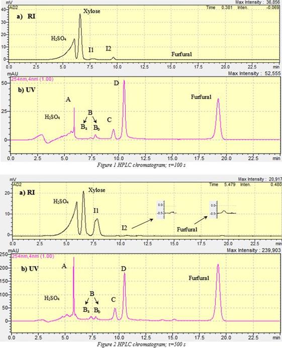
Regarding UV chromatograms (Figures 1(b) and 2(b)), peaks corresponding to compounds Ba, Bb increase from 2 and 4 mAu to 10 and 8 mAu respectively with residence time. Moreover, peak of compound C rises from 10 mAu to 50 at the end of the residence time. Finally, peak of D has a raise from 52 to 180 mAu at 500s.
3.2. Reactor performance
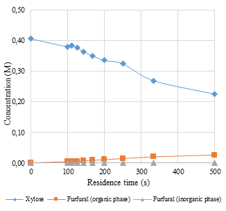
In Figure 3 the reactor outlet concentration of furfural and xylose are presented. The highest xylose conversion is 44.52 % and the overall furfural yield is 14.45 %. The selectivity towards furfural appears to be relatively constant at 35% with increasing residence time.
Figure 3 Concentration Profiles
|
Figure 4 Products Overview (inorganic phase)
|
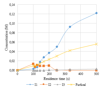
In Figure 4, the concentrations of the unknown compounds are shown as a function of residence time, with the concentration of furfural. The intermediates’ concentrations are based on the RI chromatograms (Figures 1(a) and 2(a)). However, the intermediates have not been isolated, characterized, and calibrated in the HPLC. Their concentrations are based on an estimate from their RI peak areas and overall mole balance. The RI sensitivity of I1, I2, and I3 are assumed equal and is estimated from the mole balance (Eq. (1)) for the highest conversion. The balance accuracy is more than 99.9%.

Byproducts that are not detected by the HPLC are neglected, although a very small amount of solid residue is noticed in the samples with higher residence times.
4. Discussion
It can be observed from Figures 1(a), 2(a) and 4 that component I1 shows a similar trend as furfural at higher concentration. This cannot be explained by the irreversible consecutive reaction scheme 1. It is very likely that I1 corresponds to intermediate 3 in Scheme 1 and is in equilibrium with furfural. Alternatively, all dehydration reactions (Scheme 1) are equilibrium reactions and I1 corresponds to any of the three intermediates. In Figures 1 and 2 the RI does not respond to components C and D and they are presented only in UV. Thus, it can be assumed that their concentration is low. Possibly, C and D correspond to the intermediates 2 and 3 (Scheme 1).
The concentration of component I2 increases before the lowest residence time and decreases to zero after 250s. I2 is probably a precursor to the solid residue formed and reacts with itself and the solid residue. Thus, the declining concentration with residence time can be explained. The concentration of I3 remains low and follows the same trend as furfural, which would indicate that it is a byproduct in equilibrium with I1.
5. Conclusions
By the continuous reactive extraction at 150oC, 44.52 % xylose conversion is achieved and 14.45 % total furfural yield. Compounds in equilibrium with furfural have been detected validating the theory about reaction mechanism presented earlier (Scheme 1). Moreover, additional compounds are presented in the system potentially in equilibrium with furfural intermediates. Finally, solids are formed from furfural degradation in aqueous phase even in short residence times.
6. Outlook
Future work includes additional experiments in the temperature range of 100°C to 170°C and shorter and higher residence times. Moreover, the influence of the catalyst will be investigated. Regarding the extraction part, variations will also be made on the nature and the ratio of the solvent. Finally, a kinetic model will be developed to describe the reaction rates as a function of temperature and concentrations.
7. References
1. B. Kamm, P. R. Gruber, M. Kamm. Biorefineries-Industrial processes and Products. s.l. : Wiley, 2006.
2. The Chemistry and technology of furfural production in modern lignocellulose-feedstock biorefineries. Marcotullio, Gianluca. s.l. : Delft University of technology, 2011.
3. Kinetics of furfural production by dehydration of xylose in a biphasic reactor with microwave heating. R. Weingarten, J. Cho, Wm. C. Conner, Jr. and G.W. Huber. 1423-1429, s.l. : Green Chemistry, 2010, Vol. 12.
4. Extraction of furfural from aqueous solution uding Alcohols. J. L. Cabezas, L. A. Barcena, J. Coca, M, Cockrem. 435-437, s.l. : J. Chem. Eng. Data, 1983, Vol. 33.
5. The chemistry and technology of furfural and its many by-products. Zeitch, K. J. s.l. : Elsevier, 2000.
See more of this Group/Topical: Sustainable Engineering Forum