
Key words: hollow fibre membrane, direct-flow filtration, packing density, membrane fouling, filtration resistance
Current membrane manufactures are prone to particle removal and membrane cleaning technologies because of the very challenge fouling issue that they are trying to address. It is that fouling decreases the filtration flux over time during constant pressure filtration and contrastively increases the transmembrane pressure difference (TMP) during constant flux filtration, which both restrain the productivity of the filtration process. In literature, most fouling studies have been directed to the constant pressure cross-flow filtration performances, however filtration operations with constant fluxes are more preferred in practice. This study explores the time evolution of fouling development upon design parameters of constant flux direct-flow filtration (DFF), which permits the use of smaller diameter fibres and generates less tangential flow compared with classical cross-flow filtration (CFF). DFF is usually achieved by capping one end of a CFF hollow fibre module to maintain no outlet flow from the module.
Fouling formation and its effect on filtration are influenced by various parameters, such as filtration resistance, backwash cleaning frequencies and module design parameters, out of which resistance is mostly emphasised. As reported in the literature, the rate of change of resistance is proportional to the instantaneous filtration resistance raised to a power, which varies from filtration to filtration. Hence, our investigation started with a DFF model developed by dividing the module into thousands of sections along the axial distance, which allows us to adapt a positional-changing resistance for each filtration circle. The model was validated by comparing the results with the mathematical model resulting from solution of the Navier-Stokes equations, and one group of results are given in Fig.1, Fig.2 and Fig.3. Whilst there is little evolution in the TMP profiles (Fig.1), the evolution of the resistance profile (Fig.2) results in the changing profiles of local fluxes (Fig.3). These results reflect a particular fouling model and will be contrasted with two other fouling models in the presentation. The models will be manipulated with module design parameters aiming to explain the fouling mechanism and approach for optimization of DFF.
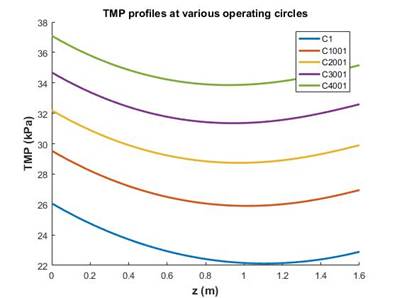
Fig. 1. The transmembrane pressure differences (TMP) upon the operating circles versus axial distance at constant flux 70 LMH. The module had a length of 1.6m and 55% packing density of 1.3mm outer diameter fibres.
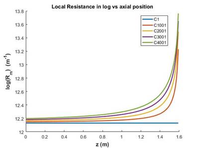
Fig. 2. The local resistance in log scale upon the operating circles versus axial distance at constant flux 70 LMH. The module had a length of 1.6m and 55% packing density of 1.3mm outer diameter fibres.
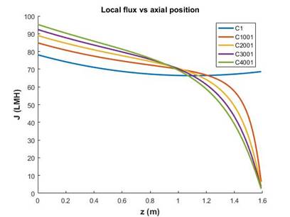
Fig. 3. The local flux upon the operating circles versus axial distance at constant flux 70 LMH. The module had a length of 1.6m and 55% packing density of 1.3mm outer diameter fibres.
See more of this Group/Topical: Separations Division