
1. Introduction
Fischer-Tropsch synthesis (FTS) is one of the main ways utilized commercially to convert natural gas, coal and biomass into liquid hydrocarbon fuels and other value-added products. The most frequently used type of reactor for FTS is a multi-tubular fixed bed reactor (FBR). Due to the high exothermicity of FTS reaction, special care has to be taken of removal of generated heat during the design of such reactors. Understanding the influence of process parameters on heat generation and removal is very important in predicting hot spots and avoiding potential temperature runaways.
Majority of previously published studies on this topic used one-dimensional pseudo-homogeneous models of FBR reactor for FTS [1]. Relatively little attention has been given to the topic of heat management, despite its practical significance. Also a common assumption was that gas-phase correlations for heat transport parameters are applicable, even though a certain amount of liquid is present both accumulated in the FTS catalyst pellets and trickling down the reactor bed.
We will present analysis of heat management characteristics in FTS fixed bed reactor using a cobalt-based catalyst. Results of a two-dimensional model simulations which incorporates the effect of both gas and liquid phase will be presented. Based on these the influence of various relevant process parameters on FTS FBR heat generation and removal will be examined.
2. Fixed-bed reactor model
The reactor model is developed as
a two-dimensional pseudo-homogeneous model without axial mixing, where
intra-particle transport is taken into account via the component effectiveness
factor  . Components
considered in the system are CO, H2, H2O and hydrocarbons
products CH4, C2, C3, C4 … C24
and lumped C25+. The main model equations are shown below.
Two-dimensional mass balance is given by:
 (1)
where  is the molar
concentration of component i (i = CO, H2, H2O
and hydrocarbons CH4, C2, … C24 and lumped C25+),
 is superficial
velocity, z and r are axial and radial dimension,
 is cross-section
area of a tube with diameter
 (
 ),
 is effective radial
diffusivity of species i, ηi is catalyst
effectiveness for species i,
 is reactor bed
density and
 is rate of
species i disappearance or formation. Rates of reactants (CO and H2)
disappearance and products (H2O, n-paraffin and 1-olefin) formation
are calculated at each point along the reactor bed using a hybrid kinetic
approach [2-4].
Heat balance equation is defined as:
 (2)
where T is
temperature,  is
reaction enthalpy per mole of CO consumed, , ρ is fluid phase
density, λer is effective radial thermal conductivity, ηco
is effectiveness factor for CO and Cp is fluid heat
capacity. Pressure drop is calculated using Ergun’s correlation [5]. Literature
correlations considering both gas and liquid phase influence on heat transport parameters
were incorporated in the model [6, 7]. The split between the gas and the liquid phase was
estimated using Raoult’s law. Effectiveness factor values were estimated based
on recent work on the single particle modeling done in our group [8].
The boundary conditions needed to solve Eqs. (1) and (2) were defined as:
 (3)
 (4)
 (5)
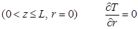 (6)
 (7)
where L is
reactor tube length, Rt is reactor tube radius,  ,
 and
 are inlet flowrate of
species i, inlet temperature and inlet pressure, respectively,
 is radial heat transfer
coefficient at the wall and
 is
wall temperature.
Model equations were discretized and solved using gPROMS software for a number of process conditions and geometric parameters.
3. Results and discussion
The influence of several process parameters (inlet flowrates and temperature, wall temperature, tube and particle diameter) on temperature distribution in radial and axial direction was investigated. At base case conditions used in our study (Tin = 473 K, Pin = 25 bar, H2/CO feed ratio = 2, Fin = 0.15 mol/s, Twall = Tin, dt = 2.6 cm, dp = 2.5 mm, L = 10 m) temperature increases in axial direction and reaches a maximum core temperature of 479 K close to the reactor inlet (z ~ 1 m), after which it decreases gradually along the reactor. The radial gradient inside the tube is about 3 K at the maximum temperature position, which highlights the importance of using two-dimensional models to represent this process.
Simulations with varying one process parameter and keeping others constant show temperature runaway occurring for Fin < 0.03 mol/s, Tin > 497 K and dt > 5.9 cm. Thermal behavior has a very complex dependency of process conditions and often variation of one parameter can have conflicting influences (both positive and negative effects) on heat management. For example, increasing inlet temperature increases the reaction rate and thus amount of generated heat. However, it also decreases the catalyst effectiveness which results in a lower amount of heat generation.
Varying inlet flowrate shows that the gas phase velocity increase has a very positive effect on the heat transfer coefficient at the wall, however the impact of gas phase composition is noticeable as well. The highest hwall values are achieved with pure syngas (i.e. inlet conditions), while generation of hydrocarbons along the reactor (XCO > 0%) changes the physical properties of the gas phase and results in hwall decrease. Increasing gas phase velocity also has a positive effect on the effective radial thermal conductivity. However, we also see a positive influence of a liquid phase velocity. The liquid phase is generated along the reactor and thus Reynolds number of liquid increases from 0 to 0.57 for the base case inlet and outlet conditions, respectively, resulting in about 18% increase of λer.
Increase of particle diameter is beneficial from standpoint of heat management, both from the perspective of decreased heat generation due to lower effectiveness factor and higher heat transport coefficients due to increased Reynolds numbers. However, this leads to low productivity and poor FTS product selectivity. Increase of tube diameter results in much higher hotspots and more likely runaways, due to higher radial thermal resistance and lower transport coefficients related to lower gas and liquid velocities. These effects can be somewhat alleviated by increasing the inlet flowrate, but not completely avoided.
4. Conclusions
Simulation results with variation of process parameters show that FTS fixed bed reactors are very sensitive in terms of heat management and any large disturbance can lead to potential temperature runaway. Reasons for this behavior of FTS fixed bed reactors are analyzed in detail. Especially interesting and previously unknown in open literature is the contribution which liquid phase has on heat transport in FTS fixed bed reactors.
References
[2] I.C. Yates and C.N. Satterfield, Energy & Fuels, 5 (1991) 168.
[4] B. Todic, W. Ma, G. Jacobs, B.H. Davis and D.B. Bukur, Catalysis Today, 228 (2014) 32.
[5] S. Ergun, Chemical Engineering Progress, 48 (1952) 89.
[6] A. Matsuura, Y. Hitaka, T. Akehata and T. Shirai, Heat Transfer - Japanse Research, 8 (1979) 44.
[7] V. Specchia, G. Baldi and S. Sicardi, Chemical Engineering Communications, 4 (1980) 361.
See more of this Group/Topical: Catalysis and Reaction Engineering Division