
Impact of hydrocarbon trapping on temperature programmed oxidation over a Pt/Pd/BEA monolith catalyst
Po-Yu Peng, Michael P. Harold*, Dan Luss**
Department of Chemical and Biomolecular Engineering, University of Houston, Houston, TX 77204
*mharold@uh.edu, **dluss@uh.edu
The function of the diesel oxidation catalyst (DOC) comprising a washcoat of Platinum (Pt) and Palladium (Pd) (PGM = precious group metals) is to catalyze the oxidation of diesel effluent mixture of CO and hydrocarbons (HCs). A DOC operates at very high CO and HC conversion (>90%) after a sufficiently high operating temperature has been reached. However, during the “cold start” a fraction of the exhaust hydrocarbons may escape unreacted [1, 2]. A large-pore zeolite such as Beta (BEA) is added to the DOC to trap diesel exhaust hydrocarbons during the cold start. High molecular weight hydrocarbons are especially prone to trapping in BEA-modified PGM DOCs. Although extensive research has been conducted on the BEA storage capacity, there is a need to gain insight on how BEA affects the performance of HC light-off (LO) and of the HC oxidation transient performance [3-7]. We conducted experiments to gain a deeper understanding of functioning of the HC trap and to enable improved trap design and operating strategy. The insight gained from this study will help optimize the multi-functional and component catalyst formulation, reactor design and operating strategy for achieving high conversion of multiple hydrocarbon species.
In a typical experiment dodecane (C12) is trapped on a 0.8 in. diameter by 3-in. long mixed washcoated Pt-Pd/BEA/Al2O3 400 cpsi cordierite monolith. The catalyst contains 60 g/ft3 PGM in a Pt:Pd ratio of 2:1 by weight (~1:1 atomic ratio) on a 0.7 g/in3 load of γ-Al2O3 support and incorporated with the BEA content (0 and 0.5 g/in3) into the washcoat. The C12 and CO2 gas concentrations were measured by spatially resolved mass spectrometry (SpaciMS, QMS-Omnistar GSD 300) and a FTIR. Spatial resolved temperature profiles were measured by a coherent optical frequency domain reflectometer (c-OFDR with a 1.26 m long gold-coated optical fiber placed in the center of monolith channel. The trapping experiments were conducted by flowing 160 ppm C12, 10% O2 and the balance Ar at 60 oC until the catalyst was saturated. This was followed by ~10 oC/min inlet temperature ramp. The total gas flowrate was 8 L/min (GHSV= 12,438 h-1). During the dynamic hysteresis analysis, the saturated catalyst was heated up by 1 oC/min from 110 oC to 170 oC inlet temperature and then cooled by -1 oC/min from 170 oC to 110 oC. The total gas flowrate varies from 6 L/min (GHSV= 10,262 h-1) and 8 L/min (GHSV= 12,438 h-1). Adiabatic behavior was confirmed by measuring temperature profiles under non-reaction conditions.
Unusual CO2 formation spikes were observed during the oxidation of HC that was pre-stored on the catalyst before exposure to the temperature ramp. Fig. 1 shows the effluent C12 concentrations along with the effluent generated CO2 concentration during a linear feed temperature ramp. The C12 is completely trapped by C12 breakthrough with a slow approach to the feed concentration value at uniform temperature of ~60 oC. However, during the subsequent temperature ramp, in addition to the release of C12 at the 48 minute mark, two impressive spikes of CO2 appeared between 50 and 57 minutes. Corresponding to the first two spikes are measureable spikes in the outlet temperature.
The c-OFDR measurements enabled construction of a 3-D contour plot of temperature versus time and position. (Figure 2) The temperature spikes correlate with the measured CO2 yield spikes. The feed temperature increased linearly during the ramp. The local temperature sequentially increased and decreased three times at a nearly fixed position in the monolith. During the first and second cooling period, the temperature went back close to the inlet temperature. This behavior suggests that the oxidation stops abrubtly as the generated heat is quickly removed by the flowing gas stream. The drop in the CO2 concentration between the first and second peaks in Fig. 1 also supports the stoppage of the HC oxidation. A mass balance analysis indicates that the fed C12 during this time period is released and re-trapped by the catalyst. The C12 continues to accumulate until that the catalyst saturates. This intermittent HC oxidation behavior continues until the HC trapping capacity becomes smaller at high temperature. The rapid propagation of the maximum temperature from the midstream to the downstream during the first peak also supports high heat convection by the gas flow. This rapid temperature peak propagation greatly accelerates the HC oxidation downstream.
A slow heating/cooling rate leads to a significant counter-clockwise hysteresis behavior, underscoring the competition between HC trapping and oxidation. Figure 3 shows the C12 and CO2 concentrations during the hysteresis under the slow heating/cooling rate of ±1 oC/min. In the ramp-up period, the C12 (CO2) gradually decreases (increases), indicating a delicate balance between trapping and oxidation. After ignition at ~159 oC, more impressive peaks occur. The occurrence of multiple peaks suggests that the C12 trapping occurs before the C12 oxidation. After a certain amount of C12 is trapped, the C12 oxidation reaction then triggers the release of stored-C12. The HC trapping capability becomes smaller at high temperatures. During the ramp-down period, a high C12 conversion remains until the feed temperature is below ~136 oC. The reactor extinguishes at ~23 oC below the ignition, showing a strong ability to reduce HC emission when the engine stalls.
The non-isothermal nature of this adiabatic system suggests that HC trapping and oxidation dominates in the different regions in the catalyst. Since the downstream is much hotter than the upstream, the HC is re-trapped by BEA at the upstream and the HC is drastically oxidizes at the downstream. Both events greatly consume the C12, helping to reduce C12 emission, and lead to a much lower extinction temperature. Even at such low heating/cooling rate of ±1 oC/min, a significant counter-clockwise hysteresis behavior still exists. This study is the first to provide insight into the spatiotemporal features of transient behavior of HC trapping and oxidation of BEA/DOC catalysts, and also the first discovery of multiple HC LO phenomena.
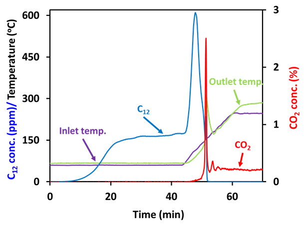
Figure 1. Dodecane and CO2 concentration measured during adsorption followed by TPO with BEA-zeolite added Pt/Pd/Al2O3 monolith catalyst. Condition during saturation: 160 ppm dodecane and 10% O2 balanced with Ar. Condition during desorption and TPO: 10% O2 balanced with Ar.
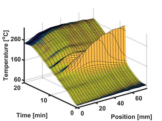
Figure 2. The 3-D plot of the spatially-resolved temperature versus time in feed of 10% O2 balanced with Ar. (Catalyst: D-05)
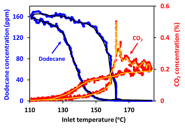
Figure 3. Experimental C12 and CO2 concentration versus inlet fluid temperature in a dynamic hysteresis analysis. (C12 = 160 ppm, 10% O2; space velocity of 12,438 h-1; temperature ramp = ±1 oC/min).
References
1. Mukai, K., et al., Adsorption and desorption characteristics of the adsorber to control the HC emission from a gasoline engine. 2004, SAE Technical Paper.
2. AL‐Harbi, M., et al., Competitive no, co and hydrocarbon oxidation reactions over a diesel oxidation catalyst. The Canadian Journal of Chemical Engineering, 2012. 90(6): p. 1527-1538.
3. Li, H.-X., et al., Application of zeolites as hydrocarbon traps in automotive emission controls. Studies in Surface Science and Catalysis, 2005. 158: p. 1375-1382.
4. Chang, H., et al., Gasoline Cold Start Concept (gCSC™) Technology for Low Temperature Emission Control. SAE Int. J. Fuels Lubr, 2014. 7(2): p. 480-488.
5. Murakami, K., et al., Development of a high performance catalyzed hydrocarbon trap using Ag-zeolite. 2004, SAE Technical Paper.
6. Elangovan, S., et al., A comparative study of zeolites SSZ-33 and MCM-68 for hydrocarbon trap applications. Microporous and mesoporous materials, 2006. 96(1): p. 210-215.
7. Elangovan, S., et al., Silicoaluminophosphate molecular sieves as a hydrocarbon trap. Applied Catalysis B: Environmental, 2005. 57(1): p. 31-36.
See more of this Group/Topical: Catalysis and Reaction Engineering Division