Monday, 24 April 2006 - 2:45 PM
64b
Development of Different Strategies of Refrigeration for Fixed Bed Catalytic Reactor: Mixed Coolant Flow as Optimal Factor
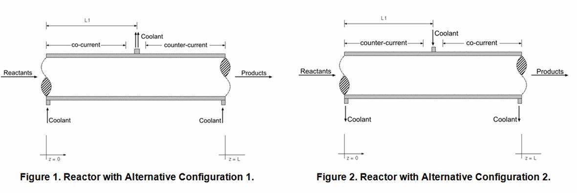
Coolant Configurations This work considers an alternate configuration for the circulation of the coolant fluid combining both concurrent and countercurrent cooling. The coolant flow is divided in two streams: one flowing co-currently while other flowing counter-currently (Figures 1 and 2). The objective is to evaluate the effect of this alternative design in the reactor performance and to compare it with the conventional cooling approaches.
1)The coolant stream flows in co-current mode in the interval from z = 0 to z = L1 and the flow is counter-current from z = L1 to z = L. This configuration is illustrated in Figure 1 and is called “Alternative Configuration 1”.
2)The coolant stream flows in counter-current mode in the interval from z = 0 to z = L1 and the flow is co-current from z = L1 to z = L. This configuration is described in Figure 2 and is called “Alternative Configuration 2”.
It should be noticed that at z = L1 the coolant stream changes direction in both schemes. Thus, the position of L1 varies for each analysis with the temperature profiles being obtained for each of such situations in both configurations. These two alternative designs have different effects on the reactor operation according to the selected L1 value. So the L1 parameter should be carefully selected. It should be pointed out that while the proposed Alternative Configuration 2 tends to be less efficient than Alternative Configuration 1, it may be useful for the case of process with side and consecutive reactions. The use of alternative coolant configurations increases the operational flexibility and it makes possible a more effective control of the reactor temperature profile. The proposed configurations take advantage of co-current cooling, near to the reactor entrance, and countercurrent operation towards the reactor exit.
See more of #64 - Simulation of Heat and Mass Transfer Equipment in Process Plants (TB001)
See more of Topical B: Energy Processes
See more of The 2006 Spring National Meeting