
Introduction
This paper will explain when one should use the ideal gas compressibility Z (equal to 1.0) or when to use the actual Z (at temperature and pressure) when sizing a relief valve using the analytical gas choked flow formula.
The proper selection of the value of Z will avoid possible over-sizing or under-sizing a relief valve.
Overview
Sizing of relief valves in gas flow is commonly performed using the analytical gas formula for choked flow. The common form used in vendor catalogues and API Standard 520-I “Sizing, Selection and Installation of Pressure-Relieving Devices” is:
W = A Kd C P ( M / T Z )0.5 (1)
Rearranging using the formula for density results in:
W = A Kd C’ ( P r )0.5 (2)
W is mass flow [lb/hr], A is orifice area [in2], Kd is discharge coefficient, P is inlet pressure [psia], M is molecular weight [lb/mole], T is Rankin temperature [°R], C is coefficient containing only the parameter K ideal gas heat capacity ratio (K = Cp / (Cp – R)), C’ is the same coefficient with revised conversion factors, r is density [lb/cf] and Z is the gas compressibility
Although deceptively simple, the assumptions inherent in the derivation may result in drastically oversized or undersized relief valves. Yet, there has been little elucidation of the issues. The results may be surprising since there are no clear resolution for certain situations.
To explain the problem, it is necessary to understand two of the major assumptions utilized in the derivation of the choked flow equation. (The derivation is quite complex but may be found in advanced transport books.)
· Gas is ideal, which means the compressibility Z is equal to 1.0 and the ratio of heat capacities is constant
· The density (as a function of pressure) is determined using a specific correlation called the “isentropic expansion expression”. This expression states that the density at the throat pressure, as the backpressure on the relief valve is reduced, may be calculated from the previous pressure and density, ideal gas heat capacity ratio K and utilizing a constant entropy process. (The subscripts 1 and 2 are used for any two pressures along an isentropic path.)
P / rK = constant (3) or stated equivalently:
P1 / r1K = P2 / r2K (4) where K is the ideal gas heat capacity ratio K = Cp / (Cp – R)
The Conundrum of Density
Equation (2) shows that the flow rate at choked condition through the relief valve is a function of density. When sizing the relief valve using the typical equation (1), the compressibility establishes the density at the initial pressure. If the gas is close to ideal, the ideal and actual densities will be comparable in value.
The densities at other pressures are implicitly represented by the “isentropic expansion expression” equation (3 or 4) which is used in the derivation of equation (1 or 2). The density pressure relationship can be demonstrated by calculating the densities utilizing the “isentropic expansion expression” equation (3 or 4). In general, they are almost a linear function of pressure since K is close to the value of one. In contrast, the actual densities frequently do not usually exhibit a linear relationship with pressure. Consequently the densities from the “isentropic expansion expression” may not track the actual densities.
Therefore accuracy of the choked gas flow rate calculation depends both on:
· the initial value of the compressibility, and on
· how well the actual densities track the densities represented by the “isentropic expansion expression”.
Examples
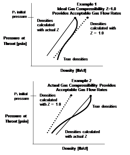 Two
examples will illustrate the differences in results, and how they are affected
by the densities. The graph plots the fluid’s density and pressure at the
relief valve orifice as the backpressure on the relief valve is reduced from
the initial pressure to a lower pressure. Three densities are plotted: 1. the
actual density (from a process simulator), 2. the density calculated from the
“isentropic expansion expression” equation (3) with the initial ideal gas density
(Z=1.0), and 3. the density calculated from the “isentropic expansion
expression” with the initial actual density.
· Example 1 provides an illustration of the situation where the ideal gas compressibility provides an acceptable sized relief valve. Although the initial ideal gas density is higher than that calculated with the actual Z, the ideal gas density curve coincides better with the actual densities.
· Example 2 illustrates the opposite situation where the actual gas compressibility provides an acceptable sized relief valve. Using the ideal gas compressibility produces higher flowrates and an oversized relief valve.
Additional examples will be provided in the presentation that will provide guidance on proper selection of the gas compressibility factor.
Conclusions
Although the homogenous direct numerical integration method (HDI) will provide the best answer in all cases, the analytical gas equation is commonly employed to size relief valves in gas service. (The HDI method is provided in API Standard 520-I “Sizing, Selection and Installation of Pressure-relieving Devices”.)
The proper selection of the value of Z when using the analytical equation will avoid possible over-sizing or under-sizing a relief valve in gas service.
See more of this Group/Topical: Global Congress on Process Safety